10. Overset
The overset descriptions begins with the basic background mesh (block 1) and overset mesh (block 2) depicted in Figure Fig. 10.1. Also shown in this figure is the reduction outer surface of block 2 (light blue). Elements within this reduced overset block will be determined by a parallel search. The collection of elements within this bounding box will be skinned to form a surface on which orphan nodes are placed. Elements within this volume are set in a new internally managed inactive block. These mesh entities are fully removed from the overall matrix for each dof. Elements within this volume are provided a masking integer element varibale of unity to select out of the visualizattion tool. Therefore, orphan nodes live at the external boundary of block 2 and along the reduced surface. The parallel search provides the mapping of orphan node and owning element from which the state can be constructed.
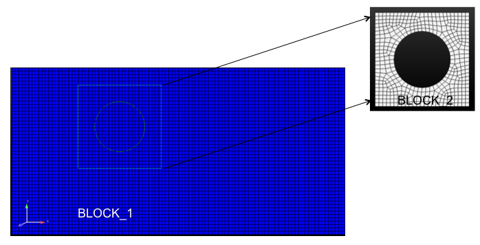
Fig. 10.1 Two-block use case describing background mesh (block 1) and overset mesh (block 2).
After the full search and overset initialization, this simple example yields the original block 1 and 2, the newly created inactive block 3, the original surface of the overset mesh and the new skinned surface (101) of the inactive block (Figure Fig. 10.2).
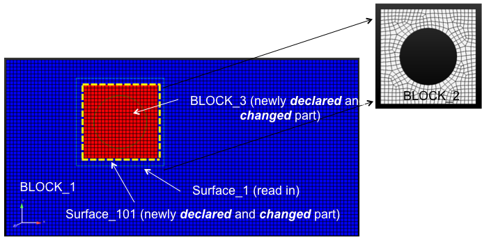
Fig. 10.2 Three-block and two surface, post over set initialization.
A simple heat conduction example is provided in Figure Fig. 10.3 where the circular boundary is set at a temperature of 500 with all external boundaries set to adiabatic.
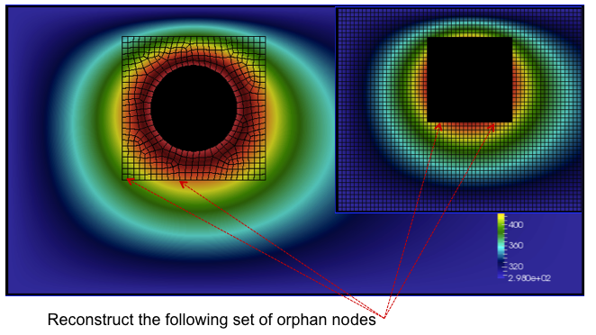
Fig. 10.3 A simple heat conduction example providing the overset mesh and donor orphan nodes.
As noted before, every orphan node lies within an owning element. Sufficient overlap is required to make the system well posed. A fully implicit procedure is provided by writing the orphan node value as a linear constraint of the owning element (Figure Fig. 10.4).
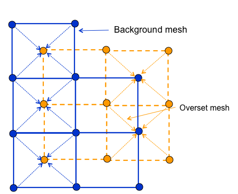
Fig. 10.4 Orphan nodes for background and overset mesh for which a fully implicit constraint equation is written.
For completeness, the constraint equation for any dof \(\phi^o\) is simply,
As noted, full sensitivities are provided in the linear system by constructing a row entry with the columns of the nodes within the owning element and the orphan node itself.
Finally, a mixed hex/tet mesh configuration example (overset mesh is tet while background is hex) is provided in Figure Fig. 10.5.
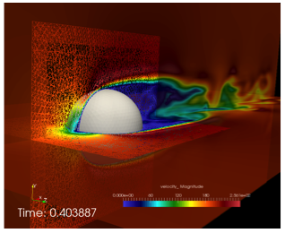
Fig. 10.5 Flow past a three-dimensional sphere using a hybrid topology (hex/tet) mesh configuration.
10.1. Future Capabilities
The overset capability has not been modified to work with generalized mesh motion. Moreover, search and cutting is reserved for simple squares and rectangular overset meshes.